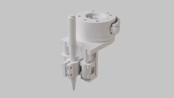
Drawing with the UR10
Prepare the image
- Open the vector image in Inkscape. Don't use Illustrator (it doesn't export the files correctly).
- Select all
Path > Object to Path- Save as. Choose
Plain SVG.- Optional: open saved file in text editor to check that there are only
<path>objects present. - Keep the filename simple and avoid spaces.
Prepare the canvas
- Flat surface: Make sure to have a mostly flat surface. The orientation doesn't matter, as long as the arm can reach it.
- Immovable surface: The surface should be fixed well, so it doesn't accidentally move.
- Measure the width and height of the image area on the surface. Keep this value for later.
Setup the physical robot
- Move the robot close the the surface.
- Stabilise the stand so it doesn't wiggle.
- Attach the drawing tool.
- Power on and check if the arm can reach the intended area using the freedrive function.

Setup RoboDK
Guide for RoboDK version 5.2.1
- On the Alienware laptop navigate to
C:\Users\formlab\Documents\FORMLAB\UR10\URplotter - Copy the vector image to this folder.
- Open file
URplotter.rdkwith RoboDK. - Delete the two bottom files:
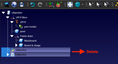
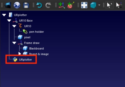
This is to make sure we're working with the newest versions. We will load the latest files from the file browser. RoboDK can be confusing since it works with cached files. - in the file browser, drag file
URplotter.pyonto the RoboDK viewport. It will be listed as a python script in the item tree.


Update the python script
We need to tell the script how big to draw, and what drawing to use.
- Right click the python script and choose
Edit Python Script. The VSCodium text editor starts up and opens the python script. - Change the variable
SIZE_BOARDto the size you would like the drawing to be (in millimeters).SIZE_BOARD = [460, 310] #Set the size of the canvas (in mm)
- Change the variable
IMAGE_FILEto the filename of the SVG image.IMAGE_FILE = 'test-image.svg'
- Press ctrl + s to save the file and go back to RoboDK. Keep in mind that this file is updated in RoboDK, but not in the file explorer. Save the changes to the file explorer if you want to keep them for the future.
Define the real world position of the canvas

The Frame draw reference frame defines the top-left corner of the image (with the blue arrow pointing towards the viewer). By defining the reference frame from real world robot poses, the real world canvas position and orientation can be set.
Power up the robot arm.

in Robodk, right-click on the UR10 robot, and choose Connect to robot.

When the connection is open the status bar turns green and shows 'Ready'. Leave the connection window open and right-click on reference frame Frame draw in the item tree and select Define Reference Frame.

Change Select Method to 3 point (P1 = origin) and set 'Calibrate using' to Joints.
Probe each point

- P1 is the left top corner of the canvas
- P2 should be somewhere on the left edge of the canvas,
- P3 should be somewhere on the canvas to the right.
Tip: if you're using a spring-loaded pen holder, add a spacer to the spring, so the pen is retracted a little bit. Then almost touch the canvast with the pen when probing. Remove the spacer before drawing.
- Move the physical robot to one of the 3 points
- You can use a combination of the freedrive function and the move controls on the teaching pendant. Note that the physical robot is locked when trying to move with freedrive. To unlock the arm, make a small movement with the teaching pendant (Move-tab) first.
- Click 'Connect'. Back in RoboDK, the connection is closed for some reason. Without closing the 'Reference Frame Definition window', click 'connect' in the connection window.
- Click 'Get Position'. When the connection status is green, click
get Positionin the connection window. The virtual robot arm should assume the same pose as the real world robot arm. - Click 'Get P1', 'Get P2' or 'Get P3'. In the 'Reference Frame Definition' window, click on
Get p1Get p2orGet p3. Pay attention to the numbers: they should change when you click the button, and they should be different than the other points.
- Repeat the last 3 steps for the remaining 2 points.
- Click 'update' when all points have been set. The virtual canvas should line up with the real world one, related to the robot base.
Send program to robot
- Generate robot program. Ctrl + click on the python program in the RoboDK item tree and choose
Generate robot program. RoboDK generates a .script-textfile that opens in the 'SciTE' text editor. - Save the file. The file is already stored in a temporary location in the finder. Find the location, or save-as to a new one.
- Import in RoboDK. Load the file back into RoboDK (drag it onto the window, and select
import programfrom the popup window). the generated program starts at a different position than RoboDK shows. Temporary fix: in the program instructions: ctrl + click on the first
change frameitem. ChooseSet Reference Link. SelectUR10 Base. Then it should work.- Connect to the robot. Open the connection to the robot in RoboDK. After the first time, it seems to work when the connection status is disconnected.
- Stand clear of the robot arm and slow down the motion on the teaching pendant.
- Send program to robot. Ctrl + click on the robot program (the text file icon with a triangle on the left) and select
Send program to robot. The robot start moving immediately.
Troubleshooting
- After 'Run Python script', nothing happens. On the left bottom of the RoboDK screen 'Running python script' is indicated. This means something is wrong with the code. Click 'Edit Python Script' and try to break the code into blocks to find the bug.
- Use the line
RDK.ShowMessage("message", popup = True)
to open a popup and pause the execution of the code at that point.
- To display variables, use this method:
msg_str = "message: %s" % variable
and use the string in ShowMessage like so:
RDK.ShowMessage(msg_str, popup = True)
- It might help to temporary load an older version of the python script, and loading the new one again after that. It sounds impossible, but it helped here before…